Disassembling Neo 1973
From Openmoko
(→Lifting the PCB on the left side: official method) |
(→Removing PCB from case frame) |
||
| (2 intermediate revisions by 2 users not shown) | |||
| Line 73: | Line 73: | ||
*Micro-SD slot | *Micro-SD slot | ||
*SIM slot - overlaying the Micro-SD slot when present. | *SIM slot - overlaying the Micro-SD slot when present. | ||
| − | * | + | *Golden GPS antenna connector. |
**Immediately above this with the grey wire connection is the connection to the built in GPS antenna. | **Immediately above this with the grey wire connection is the connection to the built in GPS antenna. | ||
| − | On the case picture below, you can see the left and right speakers under the translucent plastic, and the vibrator motor in the middle. | + | On the case picture below, you can see the left and right speakers under the translucent plastic, and the vibrator motor in the middle. Don't forget, there is only one speaker on the Neo Freerunner, not two. |
== Empty case frame == | == Empty case frame == | ||
| Line 92: | Line 92: | ||
== Display == | == Display == | ||
| − | the | + | It may be easiest to unplug the ribbon cable which connects the LCD module to the PCB, before attempting to remove the screen. To do so, unpeel the silver-grey fabric strip which passes over the ribbon conenctor and around the board edge, and then flip up the black clip which holds the ribbon in place. The clip is at the PCB end of the ribbon, and is approximately 2mm x 12mm. The ribbon can then easily be pulled out of the white socket on the PCB. When reinserting after replacing the screen, be sure the ribbon is central, square to the socket, and pushed all the way in, or the screen may not turn on. |
| − | + | The screen is fixed to the PCB by a strip of adhesive which extends the length of the module, down its centre. You will need to pry it off starting on the side opposite its connector cable. If care is taken removing it you can use it again (I used a blow dryer to heat the screen to make prying the screen from the board a little less likely to damage the unit). | |
| − | + | ||
| + | There are also four silver-grey pads, one at each corner, which support the screen, and a ribbon to the bluetooth module which passes around the PCB midway along one side. Be careful not to damage the ribbon or the pads when removing the LCD module. | ||
<span id="bottom"></span> | <span id="bottom"></span> | ||
Latest revision as of 08:41, 9 May 2012
| Neo 1973 |
|
sold out
|
|---|
| NOTE: The Disassembling the Neo1973 page shows how to open up the Neo 1973. Since the Neo FreeRunner shares the same case, this procedure applies to both. |
Contents |
[edit] Back side of Neo1973
The picture below is from the GTA01Bv3 model. The GTA01Bv4 has the Openmoko logo + OPENMOKO text below instead.
[edit] Opening back cover
To remove the back cover, put your fingernail in the small recess on the top of the Neo, and pull gently.
| NOTE: the back is not hinged, as it may appear in this picture; lift both sides away equally to avoid breaking the small tabs. |
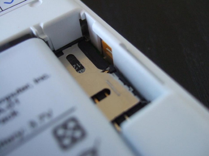
Please note the 27 x 9 x 6 mm space above the sim & memory cards after inserting the battery. This could maybe be of some use for 3rd party electronics.
| NOTE: In order to remove the front cover, you now need to remove the two Torx screws (T6x40) |
[edit] Carefully remove top cover
To remove the top cover, after removing the two Torx screws, carefully squeeze the end of the supplied guitar pick between the cover and the case at the bottom of the device, and then slide the pick up to the top on one side (do not twist the pick). As you slide the pick along, the case retaining clips should come apart with a snapping sound. Repeat the procedure for the other side of the device. To unclip the last remaining large retaining clip at the top, slide the pick all the way to the top (this can be difficult) and then press it in at the centre. By careful application of force the clip will detach and the cover can then be removed.
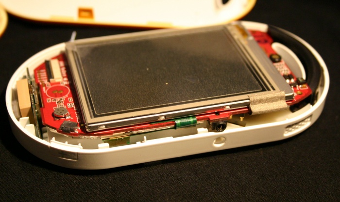
[edit] Top case lid removed
Visible in this image, from the right, going clockwise.
- The blocky device at the far right is the GPS antenna.
- To the left of this, there are two gold pads, which are where the earpiece speaker connects.
- The Debug Board connector.
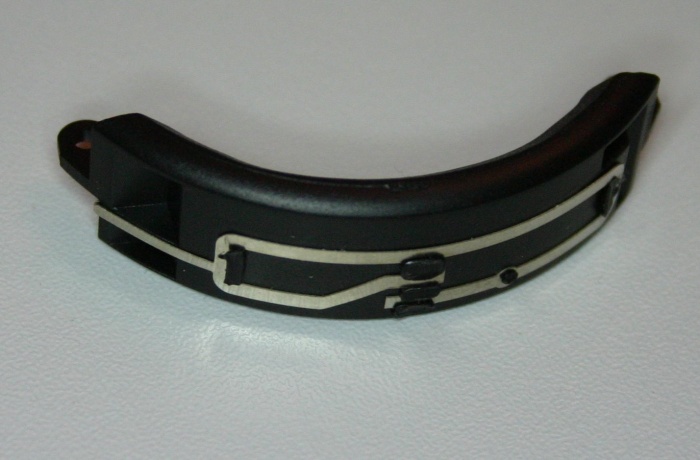
- At the left, the black semicircular device is the GSM antenna.
- Immediately to its right, the small circular black/gold object is the microphone
- At the top right, the Aux button
- Right below it seems to be a small battery. It can also be seen on the picture below.
In the middle is the touchscreen LCD, the touchscreen printed wire can be seen beginning at the bottom left of this, through the glass.
[edit] Lifting the PCB on the left side
| NOTE: You have to bend the plastic case a bit outwards until the headphone jack on the left side of the device becomes loose |
Its not shown in this picture, but I've found that it helps to slide the AUX button out of the case before trying to remove the PCB. This allows you to get a firm hold on the PCB while gently bending the case to free the headphone jack and plastic retaining clips.
The "official" method:
I suggest to use your right hand thumb fingernail to bend the case outward exactly above hs-jack (index finger next to GSM-ant, middle finger in small recess next to GPS-ant) while holding the "USB-Side" of case in the inside of your four finger base knuckles of left hand and gently pushing battery compartment base with left middle finger. Board pops out easily, takes 1sec.
Please do not use screwdriver for a lever (or similar things), this might easily break components on mainboard
[edit] Removing PCB from case frame
| NOTE: Since the PCB now is loose on one side, you can carefully pull the USB socket and GPS antenna connector out of the right side of the case, and then flip the PCB upwards |
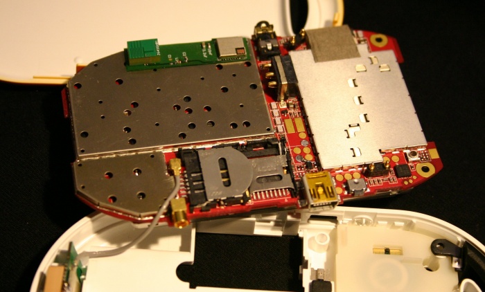
This shows:
- At the top on a green board, the bluetooth module, and the square bluetooth antenna.
- The headset jack is to the right of this.
- Immediately below the headset jack is the Neo1973 Battery connector.
- Below the Neo1973 Battery connector, the two gold pads feed the vibrator motor.
- To the right of the headset jack is the left speaker connector.
On the other side of the PCB, going from bottom-right corner down-left.
- The small circular connector is the GSM connector to which an external aerial can be connected with the back removed, or with an alternative back.
- To the left of this is the right speaker connector.
- One of the button switches.
- USB port.
- Micro-SD slot
- SIM slot - overlaying the Micro-SD slot when present.
- Golden GPS antenna connector.
- Immediately above this with the grey wire connection is the connection to the built in GPS antenna.
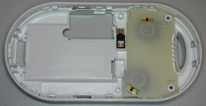
On the case picture below, you can see the left and right speakers under the translucent plastic, and the vibrator motor in the middle. Don't forget, there is only one speaker on the Neo Freerunner, not two.
[edit] Empty case frame
You can actually see the two stereo speakers beneath the translucent cover, and next to it the small vibrator motor.
Next to the top of the picture is a hole near the speaker. The external GSM antenna connector is accessed through this hole.
[edit] GSM Antenna
[edit] Display
It may be easiest to unplug the ribbon cable which connects the LCD module to the PCB, before attempting to remove the screen. To do so, unpeel the silver-grey fabric strip which passes over the ribbon conenctor and around the board edge, and then flip up the black clip which holds the ribbon in place. The clip is at the PCB end of the ribbon, and is approximately 2mm x 12mm. The ribbon can then easily be pulled out of the white socket on the PCB. When reinserting after replacing the screen, be sure the ribbon is central, square to the socket, and pushed all the way in, or the screen may not turn on.
The screen is fixed to the PCB by a strip of adhesive which extends the length of the module, down its centre. You will need to pry it off starting on the side opposite its connector cable. If care is taken removing it you can use it again (I used a blow dryer to heat the screen to make prying the screen from the board a little less likely to damage the unit).
There are also four silver-grey pads, one at each corner, which support the screen, and a ribbon to the bluetooth module which passes around the PCB midway along one side. Be careful not to damage the ribbon or the pads when removing the LCD module.
| Languages: |
English • العربية • Български • Česky • Dansk • Deutsch • Esperanto • Eesti • Español • فارسی • Suomi • Français • עברית • Magyar • Italiano • 한국어 • Nederlands • Norsk (bokmål) • Polski • Português • Română • Русский • Svenska • Slovenčina • Українська • 中文(中国大陆) • 中文(台灣) • Euskara • Català |


