Neo FreeRunner GTA02 Hardware/ru
From Openmoko
(-cats) |
(small update to current state of english page, to decide with full update oepening discussion) |
||
| Line 3: | Line 3: | ||
__NOEDITSECTION__ | __NOEDITSECTION__ | ||
{{gta02menu}} | {{gta02menu}} | ||
| − | [[Openmoko]] - это стек программного обеспечения, которое работает поверх | + | __NOTOC__ |
| + | __NOEDITSECTION__ | ||
| + | {{gta02menu}} | ||
| + | [[Openmoko]] - это стек программного обеспечения, которое работает поверх [[hardware|аппаратной платформы]]. Смартфон [[Neo FreeRunner]] - это аппаратная платформа второго поколения, которая использует Openmoko. Вы можете получить сведения относительно характериск аппаратной части, просмотрев эту вводную страницу, а также другие страницы в этой категории, приведенные в нижней части этой страницы. | ||
<!-- {{note|This page is about hardware that is currently in '''design/prototype''' phase, changes are frequent}} --> | <!-- {{note|This page is about hardware that is currently in '''design/prototype''' phase, changes are frequent}} --> | ||
| − | + | =Резюме= | |
| − | + | Openmoko, Inc. создает основанный на GNU/Linux смартфон применяя для Openmoko микропрограммное обеспечение с исходным кодом, полностью совместимым с условиями лицензии GPL. Кодовое имя проекта GTA02 (Neo FreeRunner). | |
| − | + | ||
| − | + | ||
| − | + | ||
| − | + | Детально аппаратные компоненты рассматриваются далее. См. также [[Neo FreeRunner GTA02 Hardware Requirements]] используемые для выбора этих компонентов. | |
| − | + | ||
| − | + | <gallery> | |
| + | Image:Gta02a5 pcba cs.JPG|нижняя сторона (сторона элементов) NOTE: Фотография стороны элементов в сборе A5 GTA02 | ||
| + | Image:Gta02a5 pcba ps.JPG|верхняя сторона (сторона дисплея) NOTE: Фотография стороны разводки в сборе A5 GTA02 | ||
| + | Image:GTA02 A5 PCB CS.jpg|нижняя сторона (сторона элементов) NOTE: Фотография стороны элементов печатной платы A5 GTA02 | ||
| + | Image:GTA02 A5 PCB PS.jpg|верхняя сторона (сторона дисплея) NOTE: Фотография стороны печатной платы A5 GTA02 | ||
| + | Image:SimpleComponentDiagram.jpg|Упрощённая диаграма аппаратных элементов | ||
| + | </gallery> | ||
| + | |||
| + | == Расположение элементов на печатной плате == | ||
| + | |||
| + | {| class="wikitable" cellspacing="2" cellpadding="2" style="padding: 0%; margin:0em 0em 1em 0em; border:1px solid #ffffff; background:#ffffff; width:100%;" | ||
| + | ! style="background:#ffffff;border-left:1px solid #9999cc;border-right:1px ; border-top:2px solid 75d806; border:1px solid #ffffff; width:33% " | | ||
| + | <div align=center> | ||
| + | [[Image:Gta02a5 pcba cs1.png]] | ||
| + | </div> | ||
| + | ! style="background:#ffffff;border-left:1px solid #9999cc;border-right:1px ; border-top:2px solid 75d806; border:1px solid #ffffff; width:33% " | | ||
| + | <div align=left> | ||
| + | 1. NOR Flash<br/> | ||
| + | 2. SDRAM<br/> | ||
| + | 3. GPS<br/> | ||
| + | 4. CPU/NAND Flash<br/> | ||
| + | 5. GPU<br/> | ||
| + | 6. PMU<br/> | ||
| + | 7. Audio Codec | ||
| + | </div> | ||
| + | ! style="background:#ffffff;border-left:1px solid #9999cc;border-right:1px ; border-top:2px solid 75d806; border:1px solid #ffffff; width:34% " | | ||
| + | |||
| + | <div align="left"> | ||
| + | 8. Addio Amplifier<br/> | ||
| + | 9. USB Host Power<br/> | ||
| + | 10. Analog Baseband<br/> | ||
| + | 11. Digital Baseband<br/> | ||
| + | 12. GSM SRAM/Flash<br/> | ||
| + | 13. GSM RF TRanceiver<br/> | ||
| + | 14. RF AMP | ||
| + | </div> | ||
| + | |} | ||
=Особенности= | =Особенности= | ||
Revision as of 18:16, 5 August 2008
| Languages: |
English • العربية • Български • Česky • Dansk • Deutsch • Esperanto • Eesti • Español • فارسی • Suomi • Français • עברית • Magyar • Italiano • 한국어 • Nederlands • Norsk (bokmål) • Polski • Português • Română • Русский • Svenska • Slovenčina • Українська • 中文(中国大陆) • 中文(台灣) • Euskara • Català |
Neo FreeRunner
Neo FreeRunner
Openmoko - это стек программного обеспечения, которое работает поверх аппаратной платформы. Смартфон Neo FreeRunner - это аппаратная платформа второго поколения, которая использует Openmoko. Вы можете получить сведения относительно характериск аппаратной части, просмотрев эту вводную страницу, а также другие страницы в этой категории, приведенные в нижней части этой страницы.
Резюме
Openmoko, Inc. создает основанный на GNU/Linux смартфон применяя для Openmoko микропрограммное обеспечение с исходным кодом, полностью совместимым с условиями лицензии GPL. Кодовое имя проекта GTA02 (Neo FreeRunner).
Детально аппаратные компоненты рассматриваются далее. См. также Neo FreeRunner GTA02 Hardware Requirements используемые для выбора этих компонентов.
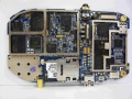
нижняя сторона (сторона элементов) NOTE: Фотография стороны элементов в сборе A5 GTA02
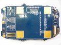
верхняя сторона (сторона дисплея) NOTE: Фотография стороны разводки в сборе A5 GTA02
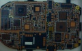
нижняя сторона (сторона элементов) NOTE: Фотография стороны элементов печатной платы A5 GTA02
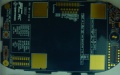
верхняя сторона (сторона дисплея) NOTE: Фотография стороны печатной платы A5 GTA02
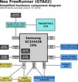
Упрощённая диаграма аппаратных элементов


Расположение элементов на печатной плате
|
|
1. NOR Flash |
8. Addio Amplifier |
|---|

Особенности
- Дисплей - Topply o2.8, 480 x 640 pixels, VGA, 200 NIT minimum, сенсорная панель резистивного типа
- Навигация интерфейса пользователя- Сенсорный экран на LCD, 2 “кнопки” управления, 1 кнопка питания, 1 дополнительная для экстренных вызывов
- Встроенный 802.11b/g приемник (Atheros chipset AR6001 Flash version)
- Встроенный Bluetooth 2.0 + EDR (CSR и поддержка PCM аудио, BC4 версия прошивки)
- Встроенный чип 2D/3D графического ускорения (S-Media 3362)
- 2 встроенных трехосных сенсора (ST акселерометр LIS302DL)
- Встроенный GPS приемник – -130 dBm с мнутренней антенной, -157 dBm судя по спецификации чипсета, TTFF по 40 секунд с -130 dBm полосой пропускания сигнала, и отслеживания (u-Blox)
- Антенна – Специализированная антенна для улучшенной работы GPS, GPRS и Wi-Fi/Bluetooth требуемой производительности, -105dBm на прием, передатчик 30dbm+2 для GSM
- Внешняя антенна – разъем MMCX GPS
- GPRS приемник – GSM/GPRS приемник. Pre-PTCRB сертифицированный модуль будет предпочтительнее
- Linux – Ядро Linux 2.6.24 или более позднее OpenMoko ядро
- USB - Переключаемый в режимы клиента и хост-контроллера (используется с целью загрузки программ), также обеспечивает питание 5в
- Питание - В обычном режиме питается через батарею 1200 mAh со встроенным счетчиком разряда, может заряжаться через специальное зарядное устройство. Внутренняя Литий-Ионная или Литий-Полимерная батарея будет поддерживать устройство в режиме ожидания. Время работы батареи (приблизительно) 150-200 часов в режиме ожидания (GSM), более 3-4 часа в режиме разговора (с погашенным экраном) (GSM)
- Светодиодные индикаторы - светодиодные индикаторы под кнопкой питания и дополнительной
Аппаратная спецификация
Основные параметры
- 400/500 MHz Samsung 2442B Processor/SOC (400 минимум)
- Код загрузчика NAND FLASH или 2MB NOR FLASH (опционально)
- 128 MB SDRAM общая, 64 MB внутри CPU, 64 MB вне
- 256MB NAND Flash MCP пакет.
Дисплей
- Topploy VGA ; диагональю 2.8”, разрешение 480 x 640 пикселей, глубина цвета 16 бит
- Качества дисплея: важное значение имеют хорошая читаемость и качественная подсветка
- Белая светодиодная подсветка. Требуемая контрастность минимум 200 NIT.
- Сенсорная панель резистивного типа.
WiFi 802.11 b/g трансивер
- Прошивка должно иметь исходники, совместимые с принципом GPL
- TX power at 11 Mbps: 13 dBm minimum
- RX sensitivity at 11 Mbps: -89 dBm desired, -83 dBm minimum
- AP mode desirable, not required
- WEP and WPA supported
- Atheros preferred because it's GPL policy
Последовательный интерфейс (UART)
- Потребовалось три последовательных интерфейса
- Консоль
- A-GPS или GPS
- GSM/GPRS
Акселерометр
- Потребовалось 2 акселерометра
- Поддерживает отключение и включение режим экономии энергии
- Трехосная чувствительность
A-GPS
- GPS chipset receiver and antenna
- Sensitivity at Antenna port: -157 dBm tracking on chipset specification
- LNA and SAW filter for maximum interference protection
- Cold start time to first fix: 40 sec typical at -130 dBm, 60 sec max
- Must support GPL for Assist-GPS function with open API
- Industry quality GPS
- Could fit in GTA01 GPS area on the PCB
Особенности GPS антенны
- Antenna is passive and internal; 15 mm x 15 mm ceramic patch is nominal design
- Antenna LNA and SAW filter are required to meet GPS performance
- 15 mm square ground plane (minimum 1 mm ground border around patch) (TBA)
- There will be one external GPS antenna connector (MMCX)
- C/N ratio should higher than 35 on production testing
Элементы управления
- Сенсорный экран поверх LCD главное устройство ввода данных
- Две “твердые” кнопки: Кнопка питания (на стороне Neo1973) механическая пластиковая кнопка, расположенная в отверстии корпуса. Дополнительная кнопка (911) на верхней части устройства, причем обе кнопки, когда они нажимаются, программному обеспечению передается пара сигналов (вкл./выкл. или нажата/не нажата). Действия при нажатии каждой кнопки определяется программным обеспечением.
- Кнопки, возможно, будут подсвечиваться
- 50000 циклов нажатия по аппаратной спецификации
Звук
- Динамик в корпусе (нужен достаточный объем и акустические характеристики окружающей среды)
- Внешнее аудио монофоническое
- Максимальное усиление: 100 dB на 5 cm обеспечивает безопасность для окружающей среды.
- Поддерживаются гарнитура и микрофон с jack-разъемом
Проектные требования по мощности
- Software based power management unit preferred
- NXP PCF series preferred
- Need support charge from USB function
- Need support powered by USB function
- Power switch: Neo1973 will have a power switch, for power on/off and suspend
- Power/Aux switch must be backlit
- Switch controls whether device is running or suspended by presses of the switch
- Switch does not shut off the power; it only suspends/resumes the device
- Internal Li-Ion or Li-Polymer battery is included. This battery supplies standby power to the device eliminates the rebooting of the device when local power is again reapplied. Battery is 1200 ma-hr.
- Battery life (Approximation) Ideal/Target Standby time 150-200 Hrs (GSM) Talk time (Backlight off) Up to 4 hrs(GSM)
- Estimated current draw for the entire device when in suspend mode (and ALL peripherals are turned off or set for deep sleep) is <5 mA at 3.6 volts (Li-Ion terminal voltage).
- GSM module deep sleep(alive and keep contact with base station) stage should take less than 8mA
- Battery will reach half capacity (~600 mAh) with 500 charge-discharge cycles. This will occur in less than 2 years of daily service.
- When powered continuously, Neo1973 must suspend (to low power mode) based either on observed low battery voltage condition or a configurable time delay.
- Neo1973 must monitor battery status while suspended and resume automatically if the charger is inserted.
- Primary power connection: 1200mAh battery
- USB charger have ID pin 47.5k pull down for Openmoko identification
- Indicators: an LED indicator visible from the side of the unit will illuminate when charging or have missing incoming call
GSM/GPRS
- 850/1800/1900 and 900/1800/1900 MHz bands must be supported
- Design should allow for multi-band version (850/900 MHz)
- Module based GPRS transceiver could meeting PTCRB and appropriate FCC certifications. It preferred that the module be pre-certified with PTCRB or OTA test
- FCC/CE certification required for GSM/GPRS part
Особенности GSM-GPRS антенны
- -105 dBm receiving on each channel (GSM/PCS)
- 30+2 dBm transmission on GSM channel
Модули Wi-Fi
- Must support GPL driver
- Atheros AR6k preferred
- Flash version required
Особенности Wi-Fi антенны
- The Wi-Fi antenna with TX 13 to 15 dBm
- RX -89 to -83 dBm @802.11b 11Mbps or an equivalent performance antenna
Bluetooth
- CSR BC4 or later solutions
USB
- Neo FreeRunner GTA02 will have USB, client/host. Using USB 1.1
- Provides USB host 5v power
- Could be powered by USB
Микрофон
1 microphone is in the device
Образ прошивки
- Using Linux 2.6.24 or later
- Could support boot from NAND or Boot from NOR
- Shipping image should come with basic phone function
- Could do full firmware upgrade by USB cable
PSN
- Device will have a PSN (product serial number) printed on the product label and machine readable in system NAND memory
IMEI
- Production phase should have IMEI code written
Package Specification
- Weight: ~150 grams with battery.
- 4 in 1 laser pen passed RoHs and safty regulation for laser equipment safty
- 1x 512MB microSD Card (SanDisk/Transcend)
- 1x USB cable Standard A to mini-B connector
- 1x 1200mAh smart/gauge battery
- Quick start guide
- 5v USB power cord w/100-240 switchable power plug
- Safety card, warranty card
- Package could pass 1m to 1.5m drop test
- AC USB charger,100v-240v, Passed UL and all required safety regulation
- Must pass FCC/CE certification
- Must pass NCC certification for Taiwan import regulation
- RoHS Compatible
- WEEE Report required
Спецификация жизненного цикла
Жизненный цикл продукта
The product is designed to last a minimum of 2 years.
Температурные условия эксплуатации
- Target operating range is –10°C to +60°C
Температурные условия хранения
- -15 deg C to +70 deg C
ESD
The device can withstand a 4.0kV contact discharge and 8.0kV air
Ударные нагрузки
Should pass 1m direct drop to concrete ground or 1.5m on slide with carpet
Аппаратные компоненты GTA02
Габаритные размеры
- 120.7 x 62 x 18.5 mm (4.75 x 2.44 x 0.728 inch)
- 110 +/- 5 g (4 ounces) without battery
Основные компоненты
Процессор
The main Processor (CPU) of the Neo1973 GTA02 is a Samsung S3C2442B B54 (running at 400 MHz)
- Product Homepage: Samsung SC32442B
- User Manual: Samsung SC32442B
- Core: ARM920T
- Instruction Set: ARMv4
- Built-in 64MB SDRAM
- Built-in 256 MB NAND
- Could run at 500Mhz
- GPIO Assignments: https://svn.openmoko.org/trunk/doc/hardware/GTA02v4/gpio.txt
- Evaluation board: S3C2442 EVB
Управление питанием
A NXP PCF50633 04 N3 is used for power management.
- NXP PMU index: NXP PMU index page
- Product Datasheet: NXP PCF50633 Product Data Sheet
- Product User manual: NXP PCF50633 User Manual
- Special thanks NXP provide full user manual and support openness for all developer
- Datasheet/User manual usage was legally authorized by NXP
- Connected to: S3C2442 via I2C, client address is 0x08.
- Driver Source: https://svn.openmoko.org/trunk/src/target/kernel/patches/pcf50633.patch
Flash
NAND Flash
256MB integrated Samsung NAND flash inside the 2442 multi-chip package, attached to the S3C2442 NAND controller
- Product Homepage: S3C2442
- Data Sheet: S3C2442 B54 comes with 256 MB NAND MCP package
- Connected to: S3C2442 NAND controller
NOR Flash
16MBit ST M58WR016KB706E NOR flash for 'unbrickable emergency boot' feature.
- Product Homepage: ST Mobile Flash NOR/Mobile Terminal
- Data Sheet: M58WR016
- Connected to: S3C2442 NAND controller
SDRAM
128MB SDRAM (64MB inside 2442 MCP, 1x Samsung K4M51323PC) attached to S3C2442 SDRAM controller
- Product Homepage: Samsung K4M51323PC
- Data Sheet: Samsung K4M51323PC
- Connected to: S3C2442
GSM/GPRS
The GSM (including GPRS) modem is Texas Instruments Calypso based.
- Connected to: S3C2442 UART1 (full-uart, RxD, TxD, CTS, RTS), /dev/ttySAC0 in userspace
- PM Driver: https://svn.openmoko.org/trunk/src/target/kernel/patches/gta01-power_control.patch
- Accessible GSM/GPRS antenna jack (if battery cover is removed)
Цифровой модулятор CALYPSO ASIC
Unfortunately we cannot provide many details on the GSM chipset due to very tight NDAs. However, this is not neccessarily required, since it interfaces using a standard UART serial line with the S3C2442. On that interface, GSM 07.05, GSM 07.10 and other standardized protocols are used.
The NDAd documentation for the calypso, register definition and hardware definition was leaked onto a public forum on the 4th of March by persons or persons unknown. The legality of reading these files may vary according to your local laws, as may generating code from them.
- Calypso D751992AZHH
- The firmware within GTA02 should be moko6 or later (internal code name)
Аналоговый модулятор TI TWL3025BZGMR
- Product Homepage: TWL3014
TI TRF6151 (GSM/PCS) RF трансивер
- Product Homepage: TRF6151
GPRS Class12/CS4
AGPS
u-blox ANTARIS 4 chip
- Connected to: S3C2442 UART2, /dev/ttySAC1 in userspace
- Driver: none needed, talks standard NMEA
- u-blox Antaris 4 Protocol Protocol download page
- ATR0635 Datasheet: u-blox ATR0635
Акселерометры
Two ST LIS302DL
- Homepage: http://www.st.com/stonline/products/literature/ds/12726/lis302dl.htm
- Datasheet: http://www.st.com/stonline/products/literature/ds/12726.pdf
- Connected to: S3C2442 via SPI interface
- S3C2442 SPI EINT interrupt inputs
Графическое/3D ускорение
Smedia Glamo 3362.
- Homepage: http://www.smediatech.com/product3362.htm
- Driver: https://svn.openmoko.org/trunk/src/target/kernel/patches/smedia-glamo.patch
- Data sheet: This is not available, as it is under NDA. It will likely never be available. (Source: Raster - IRC)
- Connected to: S3C2442 Address/Data bus
microSD
The GTA02 has one microSD aka Transflash slot. Using the Glamo 3362 MMC/SD controller
- It should support SDHC, and 4GB card has been tested. Anyone with 8GB card? MicroSD slot is under battery.
- Connected to: Glamo 3362 MMC/SD controller
- Driver: Check svn for the SMedia driver with SD implementation
- Supported microSD cards
- Specifications: SD Simplified Specification, MMC (partial), MMC (product manual)
- SANDISK 128 MB/512 MB and some 4G SDHC card been verified could work on GTA02
LCD модуль (LCM)
Toppoly (tpo) 2.8" diagonal (1.7" x 2.27" - 43mm x 58mm) 480x640 TD028TTEC1 module, using a Toshiba JBT6K74 TFT
LCD Driver Chipset.
- Homepage: Activer-Matrix-VGA.htm
- Specification: FIXME
- Driver: https://svn.openmoko.org/trunk/src/target/kernel/patches/gta01-jbt6k74.patch
- Backlight Driver: https://svn.openmoko.org/trunk/src/target/kernel/patches/gta01-backlight.patch
- Connected to: Glamo3362 LCM interface and Glamo3362 SPI Interface
Сенсорный экран
- Connected to: S3C2442 TS controller
- Driver: https://svn.openmoko.org/trunk/src/target/kernel/patches/s3c2410_touchscreen.patch
Модуль Bluetooth
Delta DFBM-CS320 Class2 Module, using CSR BlueCore4
- Data Sheet: 2.DFBM-CS320.pdf
- CSR Data Sheet: CS-101564-DSP10 BlueCore4-ROM Product Data Sheet.pdf
- Driver: Stock Linux Kernel BlueZ
- Connected to: S3C2442 USB Host controller (OHCI)
- PM Driver: https://svn.openmoko.org/trunk/src/target/kernel/patches/gta01-power_control.patch
Bluetooth аудио
This one is wired via PCM bus from the CSR Bluetooth chip to the Wolfson codec.
Модуль WiFi
Accton (WLAN 802.11b/g SiP-M WM3236AQ(Flash Ver:2.0 Atheros AR6001GZ)
- Connected to: S3C2442 SDIO Host controller
- Datasheet: Accton 3236AQ datasheet
- Driver: http://svn.openmoko.org/developers/sameo/patches/
Вибратор
- Driver: https://svn.openmoko.org/trunk/src/target/kernel/patches/gta01-vibrator.patch
- Connected to: S3C2442 GPIO
Хост USB
The USB Host controller is inside the S3C2442
- Driver: Stock Linux kernel ohci_hcd
- USB version 1.1
- Supply USB 5v in Host mode using usb power switch AAT1275IRN-5.0-T1
- A net EN_USBHOST is controlled by PMU GPIO "GPO", this one signal when asserted (high)
- enables generation of 5V for external device using a charge pump
- enables connection of 15K pulldowns to D+ and D- to allow device insertion and removal detection for host mode
- DISABLES the path for USB power to charge the battery
It should also be possible to use host mode with externally-provided power. This will allow the FreeRunner to be connected to a USB device and be powered and charging the battery if present at the same time.
- Connect 0V, d+, d-, +5 to your USB device
- Connect a 15k ohm resistor between d+ and ground
- Connect a 15k ohm resistor between d- and ground
- Connect 0V, +5 to your >1A power source
- If your power source was not the OpenMoko 1A charger, additionally connect a 47K ohm 5% resistor between the ID pin and ground to pretend to be the 1A charger.
In addition you need to make sure EN_USBHOST signal that enables the physical Host mode power generation and disables the USB -> PMU charging path is deasserted. This may be taken care of automatically shortly by detection of the 48K resistor on a USB insertion leading to forcing EN_USBHOST deasserted. The charge pump that generates the 5V in host mode doesn't seem to mind getting external 5V given to it, but the real issue is that the battery will not be charged at all if we leave EN_USBHOST asserted since one of its jobs is to stop that happening.
Устройство USB
The USB Device controller is inside the S3C2442
- Driver: https://svn.openmoko.org/trunk/src/target/kernel/patches/s3c2410_udc.patch
- Please see USB Product IDs on information about which Vendor/Product IDs we use
- 1200mAh lithium battery charges when connected to powered host.
- Mini-AB connector similar to this one.
Устройство I2C
I2C is a simple communication standard intended to move small amounts of data a few inches between chips.
Please see Neo I2C Devices for more information & a list of devices & the addresses currently in use & documented for the Neo1973.
Аудио
See also: Neo1973 Audio Subsystem
Кодек Wolfson
There's a WM8753 Wolfson Microelectronics CODEC (This is not a 'smart' codec that can interpret MP3/... it is a simple dumb 'sound card'.
- Product Homepage: http://www.wolfsonmicro.com/products/WM8753/
- Data Sheet: WM8753.pdf
- Connected to: S3C2442 IIS interface (PCM data), S3C2442 I2C (Control)
- Driver: https://svn.openmoko.org/trunk/src/target/kernel/patches/asoc.patch
Монофонический усилитель
There's a National Semiconductor LM4853 Mono Amplifier at the analog audio output of the WM8753
- Product Homepage: LM4853.html
- Data Sheet: LM4853.pdf
- Connects to (LM4853 pin):
- S3C2442 GPIO: HP_IN, AMP_SHUT (shutdown);
- Wolfson WM8753: LOUTL (LEFTIN), LOUTR (RIGHTIN);
- speaker4102: (LEFTOUT/BLTOUT-, BLTOUT+);
- headset-jack: ring 2 (RIGHTOUT), ring 3 (LEFTOUT/BLTOUT-) via 1uF-33R each
Аналоговые проводные наушники
There's a four-ring 2.5mm stereo jack which provides connectivity to old-fashioned wired headsets.
The headsets used by Motorola smartphones (A780,A1200, ...) and the V-360 have a compatible configuration.
ring
1(base): GND
2: right out
3: left out
4(tip): mic + HOLD-button(press:short to GND)
Кнопочки
The Neo1973 GTA02 features two buttons:
Корпус
The case for the FreeRunner is all black, as seen on the front page of the wiki.
Openmoko has released the CAD files for the case schematics for the OpenMoko Neo1973 (GTA01) and Neo FreeRunner. These are available in the original Pro/E (.asm/.prt) format and alternative formats created from the originals.
We welcome your assistance in providing other formats. If you are able to convert CAD files from Pro/E format to other formats, please contact [1]. We are especially interested in the DXF format and in images rendered from these files.
Аксессуары
Стилус
Using 4 in 1 laser pen
- Vendor: Quarton XPII
- GTA02 standard setup comes with QUARTON XPII 4 in 1 laser pen
Батарея
The Neo FreeRunner (GTA02) Battery is mechanically and electrically compatible with the Neo1973 GTA01 Battery, as well as limited compatibility with a Nokia BL6C battery. According to this post on the mailinglist. Photo of the battery inside the Neo1973.
- GTA02 using the smart battery based on TI bq27000 chipset
- SANYO UF653450S 1200mAh cell.
- Battery schematics: GTA02 Smart Battery Schematics
Карта microSD
GTA02 should come with one of following microSD card
Зарядное устройство
AKII Technology Charger
- Model: A10P1-05MP
- Input: 100-240v~ /0.3A
- Output: +5v up to 2.0A
- Add 47.5k 1% resistor between ID pin and ground for openmoko charger identification
История
GTA02v1
First generation of prototypes that was given to internal OpenMoko software developers. Total 30 pcs fabricated.
- It is working just fine, but still based on 2440, with external NAND/SDRAM and no NOR flash
- Using the PCF50633 05 N3 due to 04 N3 not available, re-work power for basic schematics verification
- Using GTA01 SIM socket
- Add external debug port
- Still using Global locate A-GPS
- ATAG_REVISION: 0310
GTA02v2
Second generation of prototypes, Total 50 pcs run at Taipei SMT factory MOUNT
- Ideal is have 256 MB NAND on Samsung package, Due to chip availability Start using S3C2442 B43
- Using correct PMU PCF50633 04 N3
- Change new SIM socket
- Change to u-blox A-GPS
- Change LCM power from 3.3v to 1.8v
- USB power switch layout/pin assignment mistake, could not verify USB host supply 5v function
- GPS function verified ok with good sensitivity
- ATAG_REVISION: 0320
GTA02v3
Production verification version, 2007/10/11 28 pcs fabricate at FIC SuZhou
- Still using S3C2442 B43 for hardware verification
- Using control pilot run to verify S3C2442 B54 chips
- ATAG_REVISION: 0330
GTA02v4
Mass production release candidate version 1
2 weeks after v3 gerber out, release the v4 gerber, and 2007/10/20 20 pcs fabricate at FIC SuZhou
- Change LCM power from 1.8v to 3.3v for display stability issue
- fabricate another 200 pcs for yield rate/production verification
- fabricate 50 pcs with S3C2442 B43 (128 MB NAND) for quality comparsion
- USB host power chip have some output voltage stability issues with Vb/Vcc comes from different power source, need layout change to fix the issue
- Battery Coulomb design not working on A4
- ATAG_REVISION: 0340
GTA02v5
Mass production candidate version 2/Mass production version
- First batch fabricate 2008/1/14 at FIC SuZhou
- Mass production A5 trial run start from 2008 March, including some resistor/capacitor change compare with inital 100 pcs prototypes A5, and prototypes for GTA02 developers was tracked in the Prototypes Page
- Coulomb counter issue fixed
- USB host power switch fixed
- Need add capacitor for PMU Vbat input for stability issue, this could be done by direct SMT or hand rework
- Need rework (still using SMT in production) add capacitor for PMU Vbat input for PMU stability issue.
- Need manual rework GSM IR UART path a 100k pull down for better GSM deep sleep
- ATAG_REVISION: 0350
GTA02 mass Production version change list
- PMU's LED power error: PMU potential damage issue
- NOR FLASH enable WP: User can write data into NOR FLASH.
- CE CS/RS fine tune: Audio's background noise too high
- I2C pull high resistor: The resistor is too high and signal is distorted
- GSM leakage current: TX_MODEM has a pull high resistor on IO_3V3
- Power consumption: Disable keep active function
- SDIO clock and esd protect resistor
- Refer to Datasheet: R1526 to 33K
- GSM modem on pin: The R1018 is too small and has some leakage current
- LED driving transistor: When GPIO is on, the transistor will be draw more current on LED. This is component change fix, do not need change PCB or re-work.
GTA02v6
Mass production candidate version 3/Mass production version
A6 will be fine tune version of A5, only minor schematic change for better product quality and version control. Capacitor and resistor change A6 also on mass production A5
- First 100 pcs start from 2008 mid April, and factory make component placement mistake on GSM, second 100 pcs PCB arrive time TBD.
- Add capacitor space for Vbat, reduce the SMT effort
- Add GSM IR resistor for better GSM deep sleep
- Reserve 3 GPIO for hardware version control
- Fixed LEDs power usage (from about 150mW of v5 to about 25mW)
- ATAG_REVISION: 0360
GTA02 A5 to A6 changes
- Power Glitch on VB_SYS: Add capacitor on layout, Mass production A5 also apply this change.
- G-sensor separate these interrupt pins: At A5, each accelerometer INT1/INT2 connected to same line, at A6 only INT1 was connected.
- GSM_modem power source Reduce power's ripple when the phone is talking
- Keep active Disable keep active function, just fine tune
- GPIO for version control
- GSM RX_IR has some noise Add resistor and reduce GSM RX_IR noise and gsm can't enter suspend mode easily, apply on mass production A5.
- LED driving transistor apply on mass production A5.
- LCM's VDDIO We can totally power off LCM's power, save about extra 1mA.
Отладочная плата
Описание соединения отладочной платы
This is the connector used to connect the Debug Board and possibly other hardware.
Connections are:
- 39 - GND
- 38 - STDI
- 37 - _RESET
- 36 - STMS
- 35 - STCK
- 34 - STDO
- 33 - GSM_EN
- 29 - _STRST
- 19 - X_I2C_SCL (H-TP4703)
- 18 - X_I2C_SDA (H-TP4704)
- 17 - SPI_CLK0
- 16 - SPI_MOSI0
- 15 - SPI-MISO0
- 14 - SS0
- 13 - EINT3 (H-TP4705)
- 3 - CONSOLE_TXD (H-TP4701)
- 2 - CONSOLE_RXD (H-TP4702)
Information from [2].
![[2]](http://people.openmoko.org/roh/Debugport_GTA01bv4.png)
Отличия аппаратных изменений
Inside the Bootloader
Every hardware revision has its own u-boot image type. Thus, the bootloader has the revision hard-coded. The hardware revision is passed on to the kernel via the ATAG mechanism (ATAG_REVISION)
Inside the Kernel
The kernel receives the ATAG_REVISION during bootup, and saves its contents in the "system_rev" global variable.
From Userspace
The kernel exports the system_rev variable in /proc/cpuinfo as "Revision :" line.
Certification
FCC
- For US Import
- 850/1800/1900 Band, FCC ID: EUNGTA02
- 900/1800/1900 Band, FCC ID: EUNGTA02E
- FCC test report(GTA02)
- FCC test report(GTA02E)
CE
- For Europe
- Registration number: M528583V-EO
- CE report and certificate
NCC
- For Taiwan Import
- NCC certification number: CCAF08DG0080T0
- NCC report and certificate