Neo FreeRunner GTA02 Hardware/it
From Openmoko
| Languages: |
English • العربية • Български • Česky • Dansk • Deutsch • Esperanto • Eesti • Español • فارسی • Suomi • Français • עברית • Magyar • Italiano • 한국어 • Nederlands • Norsk (bokmål) • Polski • Português • Română • Русский • Svenska • Slovenčina • Українська • 中文(中国大陆) • 中文(台灣) • Euskara • Català |
Neo FreeRunner
Openmoko is a software distribution stack that sits on top of a hardware platform. The Neo FreeRunner phone is the second hardware platform to take advantage of Openmoko. You can find specifications of the hardware by reviewing this introduction page and the pages in the category as shown at the bottom of this page.
Summary
Openmoko, Inc. ha costruito uno smarth phone basato su Linux compatibile pienamente con il codice d'origine per Openmoko, sotto licenza GPL, progetto chiamato GTA02 (Neo FreeRunner).
Qui sotto può essere trovata una lista dettagliata dei componenti hardware.Leggi anche Neo FreeRunner GTA02 Hardware Requirements usato per creare questa selezione di componenti.
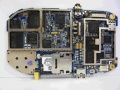
display (top) side NOTE: GTA02 A5 PCBA foto lato Componenti
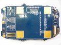
component (back) side NOTE: GTA02 A5 PCBA foto lato Stampato
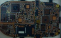
component (back) side NOTE: GTA02 A5 PCB foto lato Componenti
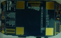
component (back) side NOTE: GTA02 A5 PCB foto lato Stampato
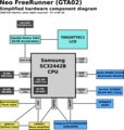
Diagramma Semplificato dei Componenti Hardware


GTA02 Selezione Componenti Hardware
Dimensioni
- 120.7 x 62 x 18.5 mm (4.75 x 2.44 x 0.728 inch)
- 110 +/- 5 g (4 oncie) senza batteria
Componenti Principali
Processore
Il processore principale (CPU) è un Samsung S3C2442B B54 (400 MHz)
GPIO Assignmenti: https://svn.openmoko.org/trunk/doc/hardware/GTA02v4/gpio.txt
Risorse Energia
Un NXP PCF50633 04 N3 è usato per power management.
- NXP PMU index: NXP PMU index page
- Product Datasheet: NXP PCF50633 Product Data Sheet
- Manuale del prodotto per l'utente: NXP PCF50633 User Manual
- Un ringraziamento speciale a NXP per aver fornito pien manuale e supporto aperto a tutti gli sviluppatori
- Datasheet/User manual usage was legally authorized by NXP
- Connected to: S3C2442 via I2C, client address is 0x08.
- Driver Source: https://svn.openmoko.org/trunk/src/target/kernel/patches/pcf50633.patch
Flash
NAND Flash
256MB integrata Samsung NAND flash all'interno del 2442 multi-chip package, attaccato al S3C2442 NAND controller
- Homepage del prodotto: S3C2442
- Data Sheet: S3C2442 B54 comes with 256 MB NAND MCP package
- Connesso a: S3C2442 NAND controller
NOR Flash
16MBit ST M58WR016KB706E NOR flash for 'unbrickable emergency boot' feature.
- Product Homepage: ST Mobile Flash NOR/Mobile Terminal
- Data Sheet: M58WR016
- Connected to: S3C2442 NAND controller
SDRAM
128MB SDRAM (64MB inside 2442 MCP, 1x Samsung K4M51323PC) attached to S3C2442 SDRAM controller
- Product Homepage: Samsung K4M51323PC
- Data Sheet: Samsung K4M51323PC
- Connected to: S3C2442
GSM/GPRS
The GSM (including GPRS) modem is Texas Instruments Calypso based.
- Connected to: S3C2442 UART1 (full-uart, RxD, TxD, CTS, RTS), /dev/ttySAC0 in userspace
- PM Driver: https://svn.openmoko.org/trunk/src/target/kernel/patches/gta01-power_control.patch
- Accessible GSM/GPRS antenna jack (if battery cover is removed)
CALYPSO ASIC digital baseband
Unfortunately we cannot provide many details on the GSM chipset due to very tight NDAs. However, this is not neccessarily required, since it interfaces using a standard UART serial line with the S3C2442. On that interface, GSM 07.05, GSM 07.10 and other standardized protocols are used.
The NDAd documentation for the calypso, register definition and hardware definition was leaked onto a public forum on the 4th of March by persons or persons unknown. The legality of reading these files may vary according to your local laws, as may generating code from them.
- Calypso D751992AZHH
- The firmware within GTA02 should be moko6 or later (internal code name)
TI TWL3025BZGMR analog baseband
- Product Homepage: TWL3014
TI TRF6151 (GSM/PCS) RF Transceiver
- Product Homepage: TRF6151
GPRS Class12/CS4
AGPS
- Connected to: S3C2442 UART2, /dev/ttySAC1 in userspace
Accelerometers
Two ST LIS302DL
- Homepage: http://www.st.com/stonline/products/literature/ds/12726/lis302dl.htm
- Datasheet: http://www.st.com/stonline/products/literature/ds/12726.pdf
- Connected to: S3C2442 via SPI interface
- S3C2442 SPI EINT interrupt inputs
Graphics/3D Acceleration
Smedia Glamo 3362.
- Homepage: http://www.smediatech.com/product3362.htm
- Driver: https://svn.openmoko.org/trunk/src/target/kernel/patches/smedia-glamo.patch
- Data sheet: This is not available, as it is under NDA. It will likely never be available. (Source: Raster - IRC). There is hope that the glamo chip features may be usable even without a NDA, see the hack here
- Connected to: S3C2442 Address/Data bus
microSD
The GTA02 has one microSD aka Transflash slot. Using the Glamo 3362 MMC/SD controller
- It should support SDHC, and 4GB card has been tested. Anyone with 8GB card? MicroSD slot is under battery.
- Connected to: Glamo 3362 MMC/SD controller
- Driver: Check svn for the SMedia driver with SD implementation
- Supported microSD cards
- Specifications: SD Simplified Specification, MMC (partial), MMC (product manual)
- SANDISK 128 MB/512 MB and some 4G SDHC card been verified could work on GTA02
LCD Module (LCM)
Toppoly (tpo) 2.8" diagonal (1.7" x 2.27" - 43mm x 58mm) 480x640 TD028TTEC1 module, using a Toshiba JBT6K74 TFT
LCD Driver Chipset.
- Homepage: Activer-Matrix-VGA.htm
- Specification: FIXME
- Driver: https://svn.openmoko.org/trunk/src/target/kernel/patches/gta01-jbt6k74.patch
- Backlight Driver: https://svn.openmoko.org/trunk/src/target/kernel/patches/gta01-backlight.patch
- Connected to: Glamo3362 LCM interface and Glamo3362 SPI Interface
Touch Screen
- Connected to: S3C2442 TS controller
- Driver: https://svn.openmoko.org/trunk/src/target/kernel/patches/s3c2410_touchscreen.patch
Bluetooth Module
Delta DFBM-CS320 Class2 Module, using CSR BlueCore4
- Data Sheet: 2.DFBM-CS320.pdf
- CSR Data Sheet: CS-101564-DSP10 BlueCore4-ROM Product Data Sheet.pdf
- Driver: Stock Linux Kernel BlueZ
- Connected to: S3C2442 USB Host controller (OHCI)
- PM Driver: https://svn.openmoko.org/trunk/src/target/kernel/patches/gta01-power_control.patch
Bluetooth Audio
This one is wired via PCM bus from the CSR Bluetooth chip to the Wolfson codec.
WiFi Module
Accton (WLAN 802.11b/g SiP-M WM3236AQ(Flash Ver:2.0 Atheros AR6001GZ)
- Connected to: S3C2442 SDIO Host controller
- Datasheet: Accton 3236AQ datasheet
- Driver: http://svn.openmoko.org/developers/sameo/patches/
Vibrator
- Driver: https://svn.openmoko.org/trunk/src/target/kernel/patches/gta01-vibrator.patch
- Connected to: S3C2442 GPIO
USB Host
The USB Host controller is inside the S3C2442
- Driver: Stock Linux kernel ohci_hcd
- USB version 1.1
- Supply USB 5v in Host mode using usb power switch AAT1275IRN-5.0-T1
- A net EN_USBHOST is controlled by PMU GPIO "GPO", this one signal when asserted (high)
- enables generation of 5V for external device using a charge pump
- enables connection of 15K pulldowns to D+ and D- to allow device insertion and removal detection for host mode
- DISABLES the path for USB power to charge the battery
It should also be possible to use host mode with externally-provided power. This will allow the FreeRunner to be connected to a USB device and be powered and charging the battery if present at the same time.
- Connect 0V, d+, d-, +5 to your USB device
- Connect a 15k ohm resistor between d+ and ground
- Connect a 15k ohm resistor between d- and ground
- Connect 0V, +5 to your >1A power source
- If your power source was not the Openmoko 1A charger, additionally connect a 47K ohm 5% resistor between the ID pin and ground to pretend to be the 1A charger.
In addition you need to make sure EN_USBHOST signal that enables the physical Host mode power generation and disables the USB -> PMU charging path is deasserted. This may be taken care of automatically shortly by detection of the 48K resistor on a USB insertion leading to forcing EN_USBHOST deasserted. The charge pump that generates the 5V in host mode doesn't seem to mind getting external 5V given to it, but the real issue is that the battery will not be charged at all if we leave EN_USBHOST asserted since one of its jobs is to stop that happening.
USB Device
The USB Device controller is inside the S3C2442
- Driver: https://svn.openmoko.org/trunk/src/target/kernel/patches/s3c2410_udc.patch
- Please see USB Product IDs on information about which Vendor/Product IDs we use
- 1200mAh lithium battery charges when connected to powered host.
- Mini-AB connector similar to this one.
I2C Devices
I2C is a simple communication standard intended to move small amounts of data a few inches between chips.
Please see Neo I2C Devices for more information & a list of devices & the addresses currently in use & documented for the Neo1973.
Audio
See also: Neo1973 Audio Subsystem
Wolfson Codec
There's a WM8753 Wolfson Microelectronics CODEC (This is not a 'smart' codec that can interpret MP3/... it is a simple dumb 'sound card'.)
- Product Homepage: http://www.wolfsonmicro.com/products/WM8753/
- Data Sheet: WM8753.pdf
- Connected to: S3C2442 IIS interface (PCM data), S3C2442 I2C (Control)
- Driver: https://svn.openmoko.org/trunk/src/target/kernel/patches/asoc.patch
Mono Amplifier
There's a National Semiconductor LM4853 Mono Amplifier at the analog audio output of the WM8753
- Product Homepage: LM4853.html
- Data Sheet: LM4853.pdf
- Connects to (LM4853 pin):
- S3C2442 GPIO: HP_IN, AMP_SHUT (shutdown);
- Wolfson WM8753: LOUTL (LEFTIN), LOUTR (RIGHTIN);
- speaker4102: (LEFTOUT/BLTOUT-, BLTOUT+);
- headset-jack: ring 2 (RIGHTOUT), ring 3 (LEFTOUT/BLTOUT-) via 1uF-33R each
Analog wired Headset
There's a four-ring 2.5mm stereo jack which provides connectivity to old-fashioned wired headsets.
The headsets used by Motorola smartphones (A780,A1200, ...) and the V-360 have a compatible configuration.
ring
1(base): GND
2: right out
3: left out
4(tip): mic + HOLD-button(press:short to GND)
Buttons
The Neo1973 GTA02 features two buttons:
Case
The case for the FreeRunner is all black, as seen on the front page of the wiki.
Openmoko has released the CAD files for the case schematics for the Openmoko Neo1973 (GTA01) and Neo FreeRunner. These are available in the original Pro/E (.asm/.prt) format and alternative formats created from the originals.
We welcome your assistance in providing other formats. If you are able to convert CAD files from Pro/E format to other formats, please contact [1]. We are especially interested in the DXF format and in images rendered from these files.
Accessory
Stylus
Using 4 in 1 laser pen
- Vendor: Quarton XPII
- GTA02 standard setup comes with QUARTON XPII 4 in 1 laser pen
Battery
The Neo FreeRunner (GTA02) Battery is mechanically and electrically compatible with the Neo1973 GTA01 Battery, as well as limited compatibility with a Nokia BL6C battery. According to this post on the mailinglist. Photo of the battery inside the Neo1973.
- GTA02 using the smart battery based on TI bq27000 chipset
- SANYO UF653450S 1200mAh cell.
- Battery schematics: GTA02 Smart Battery Schematics
microSD Card
GTA02 should come with one of following microSD card
Charger
AKII Technology Charger
- Model: A10P1-05MP
- Input: 100-240v~ /0.3A
- Output: +5v up to 2.0A
- Add 47.5k 1% resistor between ID pin and ground for openmoko charger identification
History
GTA02v1
First generation of prototypes that was given to internal Openmoko software developers. Total 30 pcs fabricated.
- It is working just fine, but still based on 2440, with external NAND/SDRAM and no NOR flash
- Using the PCF50633 05 N3 due to 04 N3 not available, re-work power for basic schematics verification
- Using GTA01 SIM socket
- Add external debug port
- Still using Global locate A-GPS
- ATAG_REVISION: 0310
GTA02v2
Second generation of prototypes, Total 50 pcs run at Taipei SMT factory MOUNT
- Ideal is have 256 MB NAND on Samsung package, Due to chip availability Start using S3C2442 B43
- Using correct PMU PCF50633 04 N3
- Change new SIM socket
- Change to u-blox A-GPS
- Change LCM power from 3.3v to 1.8v
- USB power switch layout/pin assignment mistake, could not verify USB host supply 5v function
- GPS function verified ok with good sensitivity
- ATAG_REVISION: 0320
GTA02v3
Production verification version, 2007/10/11 28 pcs fabricate at FIC SuZhou
- Still using S3C2442 B43 for hardware verification
- Using control pilot run to verify S3C2442 B54 chips
- ATAG_REVISION: 0330
GTA02v4
Mass production release candidate version 1
2 weeks after v3 gerber out, release the v4 gerber, and 2007/10/20 20 pcs fabricate at FIC SuZhou
- Change LCM power from 1.8v to 3.3v for display stability issue
- fabricate another 200 pcs for yield rate/production verification
- fabricate 50 pcs with S3C2442 B43 (128 MB NAND) for quality comparsion
- USB host power chip have some output voltage stability issues with Vb/Vcc comes from different power source, need layout change to fix the issue
- Battery Coulomb design not working on A4
- ATAG_REVISION: 0340
GTA02v5
Mass production candidate version 2/Mass production version
- First batch fabricate 2008/1/14 at FIC SuZhou
- Mass production A5 trial run start from 2008 March, including some resistor/capacitor change compare with inital 100 pcs prototypes A5, and prototypes for GTA02 developers was tracked in the Prototypes Page
- Coulomb counter issue fixed
- USB host power switch fixed
- Need add capacitor for PMU Vbat input for stability issue, this could be done by direct SMT or hand rework
- Need rework (still using SMT in production) add capacitor for PMU Vbat input for PMU stability issue.
- Need manual rework GSM IR UART path a 100k pull down for better GSM deep sleep
- ATAG_REVISION: 0350
GTA02 mass Production version change list
- PMU's LED power error: PMU potential damage issue
- NOR FLASH enable WP: User can write data into NOR FLASH.
- CE CS/RS fine tune: Audio's background noise too high
- I2C pull high resistor: The resistor is too high and signal is distorted
- GSM leakage current: TX_MODEM has a pull high resistor on IO_3V3
- Power consumption: Disable keep active function
- SDIO clock and esd protect resistor
- Refer to Datasheet: R1526 to 33K
- GSM modem on pin: The R1018 is too small and has some leakage current
- LED driving transistor: When GPIO is on, the transistor will be draw more current on LED. This is component change fix, do not need change PCB or re-work.
GTA02v6
Mass production candidate version 3/Mass production version
A6 will be fine tune version of A5, only minor schematic change for better product quality and version control. Capacitor and resistor change A6 also on mass production A5
- First 100 pcs start from 2008 mid April, and factory make component placement mistake on GSM, second 100 pcs PCB arrive time TBD.
- Add capacitor space for Vbat, reduce the SMT effort
- Add GSM IR resistor for better GSM deep sleep
- Reserve 3 GPIO for hardware version control
- Fixed LEDs power usage (from about 150mW of v5 to about 25mW)
- ATAG_REVISION: 0360
GTA02 A5 to A6 changes
- Power Glitch on VB_SYS: Add capacitor on layout, Mass production A5 also apply this change.
- G-sensor separate these interrupt pins: At A5, each accelerometer INT1/INT2 connected to same line, at A6 only INT1 was connected.
- GSM_modem power source Reduce power's ripple when the phone is talking
- Keep active Disable keep active function, just fine tune
- GPIO for version control
- GSM RX_IR has some noise Add resistor and reduce GSM RX_IR noise and gsm can't enter suspend mode easily, apply on mass production A5.
- LED driving transistor apply on mass production A5.
- LCM's VDDIO We can totally power off LCM's power, save about extra 1mA.
Debug Board
Debug Board Connector definition
This is the connector used to connect the Debug Board and possibly other hardware.
Connections are:
- 39 - GND
- 38 - STDI
- 37 - _RESET
- 36 - STMS
- 35 - STCK
- 34 - STDO
- 33 - GSM_EN
- 29 - _STRST
- 19 - X_I2C_SCL (H-TP4703)
- 18 - X_I2C_SDA (H-TP4704)
- 17 - SPI_CLK0
- 16 - SPI_MOSI0
- 15 - SPI-MISO0
- 14 - SS0
- 13 - EINT3 (H-TP4705)
- 3 - CONSOLE_TXD (H-TP4701)
- 2 - CONSOLE_RXD (H-TP4702)
Information from [2].
![[2]](http://people.openmoko.org/roh/Debugport_GTA01bv4.png)
Distinguishing hardware revisions
Inside the Bootloader
Every hardware revision has its own u-boot image type. Thus, the bootloader has the revision hard-coded. The hardware revision is passed on to the kernel via the ATAG mechanism (ATAG_REVISION)
Inside the Kernel
The kernel receives the ATAG_REVISION during bootup, and saves its contents in the "system_rev" global variable.
From Userspace
The kernel exports the system_rev variable in /proc/cpuinfo as "Revision :" line.
Certification
FCC
- For US Import
- 850/1800/1900 Band, FCC ID: EUNGTA02
- 900/1800/1900 Band, FCC ID: EUNGTA02E
- FCC test report(GTA02)
- FCC test report(GTA02E)
CE
- For Europe
- Registration number: M528583V-EO
- CE report and certificate
NCC
- For Taiwan Import
- NCC certification number: CCAF08DG0080T0
- NCC report and certificate