Disassembling Neo 1973
From Openmoko
(→Removing PCB from case frame) |
(→Removing PCB from case frame: Add text explaining what all the connectors are.) |
||
| Line 32: | Line 32: | ||
*To the right of the headset jack is the left speaker connector. | *To the right of the headset jack is the left speaker connector. | ||
| + | Invisible | ||
On the other side of the PCB, going from bottom-right corner down-left. | On the other side of the PCB, going from bottom-right corner down-left. | ||
| Line 43: | Line 44: | ||
**Immediately above this with the grey wire connection is the connection to the built in GPS antenna. | **Immediately above this with the grey wire connection is the connection to the built in GPS antenna. | ||
| − | On the case, | + | On the case picture below, you can see the left and right speakers under the translucent plastic, and the vibrator motor in the middle. |
== Empty case frame == | == Empty case frame == | ||
Revision as of 21:33, 15 February 2007
Disassembling the Neo1973
| NOTE: This page was written as of GTA01Bv3 hardware revision and might need updating soon |
Contents |
Back side of Neo1973
Opening back cover
| NOTE: You now need to remove the two Torx screws (T6x40) |
Carefully remove top cover
Top case lid removed
Lifting the PCB on the left side
| NOTE: You have to bend the plastic case a bit outwards until the headphone jack on the left side of the device becomes loose |
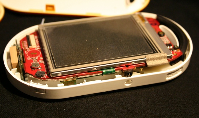
Removing PCB from case frame
| NOTE: Since the PCB now is loose on one side, you can carefully pull the USB socket and GPS antenna connector out of the right side of the case, and then flip the PCB upwards |
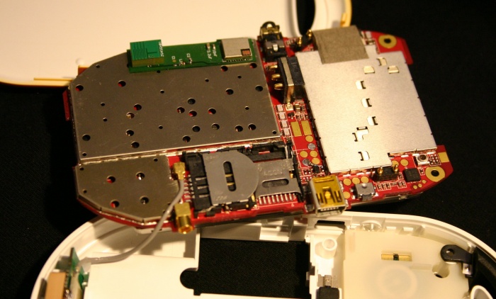
This shows:
- At the top on a green board, the bluetooth module, and the square bluetooth antenna.
- The headset jack is to the right of this.
- Immediately below the headset jack is the battery connector.
- Below the battery connector, the two gold pads feed the vibrator motor.
- To the right of the headset jack is the left speaker connector.
Invisible On the other side of the PCB, going from bottom-right corner down-left.
- The small circular connector is the GSM connector to which the ariel connects.
- To the left of this is the right speaker connector.
- One of the button switches.
- USB port.
- Micro-SD slot
- SIM slot - overlaying the Micro-SD slot when present.
- Gold GSM antenna connector. (or is this GPS?)
- Immediately above this with the grey wire connection is the connection to the built in GPS antenna.
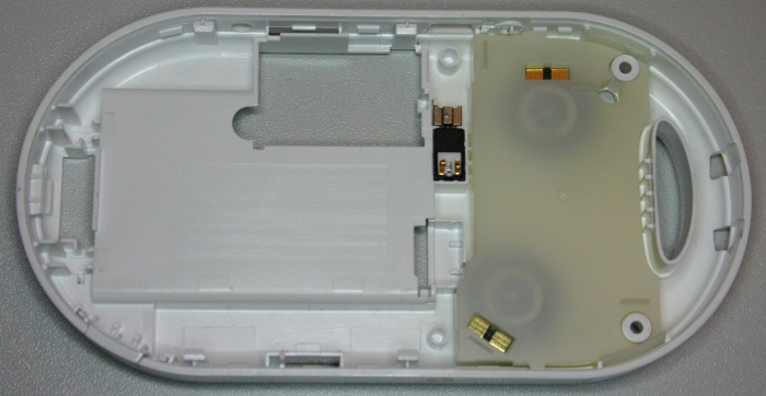
On the case picture below, you can see the left and right speakers under the translucent plastic, and the vibrator motor in the middle.
Empty case frame
You can actually see the two stereo speakers beneath the translucent cover, and next to it the small vibrator motor.


